LinACE™ vs. magnetostrictive encoders with SSI output
LinACE™와 자기 변형 센서는 유사한 분야에 사용할 수 있습니다. 그러나 둘 사이에는 몇 가지 중요한 차이점이 있습니다.
자기 변형 센서는 자기 변형 원리를 사용해서 위치를 결정합니다. 이 센서는 강자성 도파관, 위치 마그넷, 댐핑 존 및 스트레인 펄스 변환기(측정 전자부품 포함)로 구성됩니다. 전류 펄스가 도파관에 적용되며, 도파관은 이동하는 위치 마그넷에 의해 생성된 자기장과 상호 작용하는 방사상 자기장을 생성합니다.
이 상호 작용은 양방향으로 도파관으로 따라 전파되는 비틀림 스트레인 펄스를 유발합니다. 가이드의 한쪽 끝에서 펄스가 감쇠되고, 다른쪽 끝에서 스트레인 펄스 컨버터에 의해 전기 신호로 변환됩니다.
전류 펄스 트리거링과 전기 신호 수신 사이에 경과하는 시간에 따라, 이동하는 위치 마그넷의 정확한 위치를 계산할 수 있습니다.
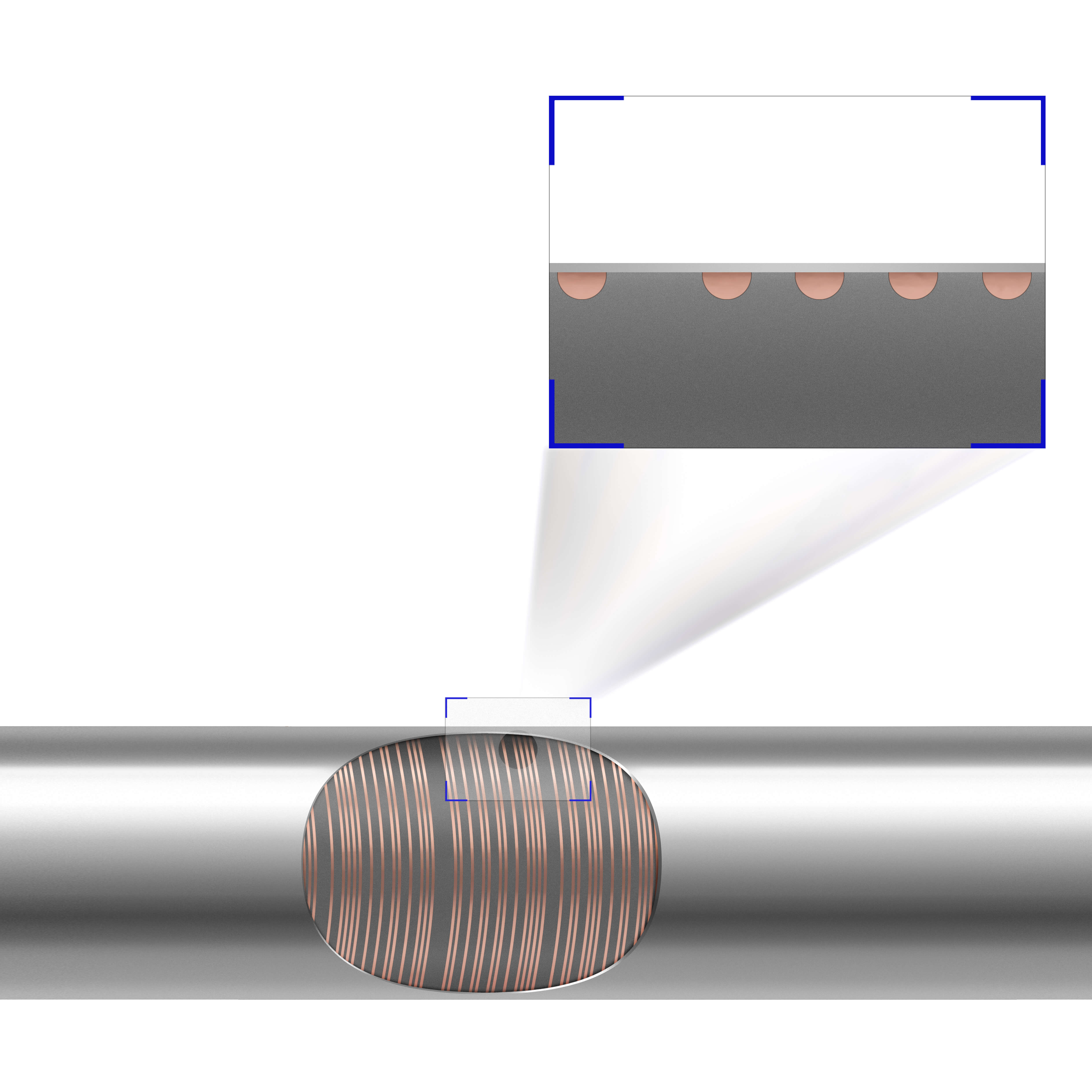
LinACE 센서는 위치를 인코딩하는 코드 캐리어 또는 스케일과 페어링되는 엔코더 또는 판독 헤드입니다. 코딩된 샤프트는 스케일로 동작합니다.
자기 변형 센서 대신 LinACE 엔코더를 선택해야 하는 이유는 무엇일까요?
자세한 내용은 LinACE 웹사이트에서 확인할 수 있습니다.
높은 정밀도
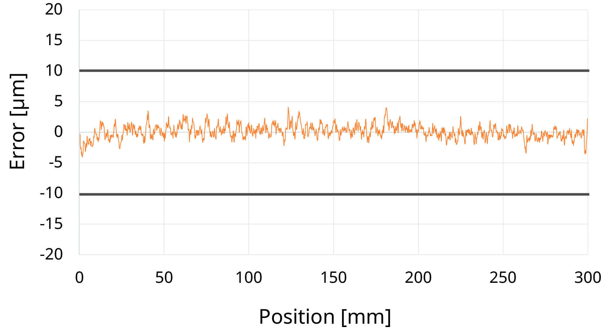
LinACE 엔코더는 10 µm ~ 0.5 µm의 분해능과 ±100 µm ~ ±5 µm의 정확도로 제공됩니다. 최대 100 mm의 측정 길이에 대해 정확도가 ±5 µm이고, 최대 450 mm의 측정 길이에 대해 정확도가 ±10 µm입니다.
측정 길이 100 mm, 정확도 ±5 µm에 대한 일반적인 정확도가 다음 그래프에 나타나 있습니다.
LinACE 정확도 그래프
그러나 코딩된 샤프트와 알루미늄 하우징의 열 팽창으로 인한 온도 변이를 고려해야 합니다.
또한 자기 변형 엔코더가 0.5 µm의 분해능을 가질 수 있습니다. 하지만 자기 변형 엔코더의 경우 선형성은 지정되지만 정확도는 지정되지 않습니다. 최대 길이 500 mm의 경우, 일반적인 선형성은 ±40 µm 또는 ±50 µm입니다.
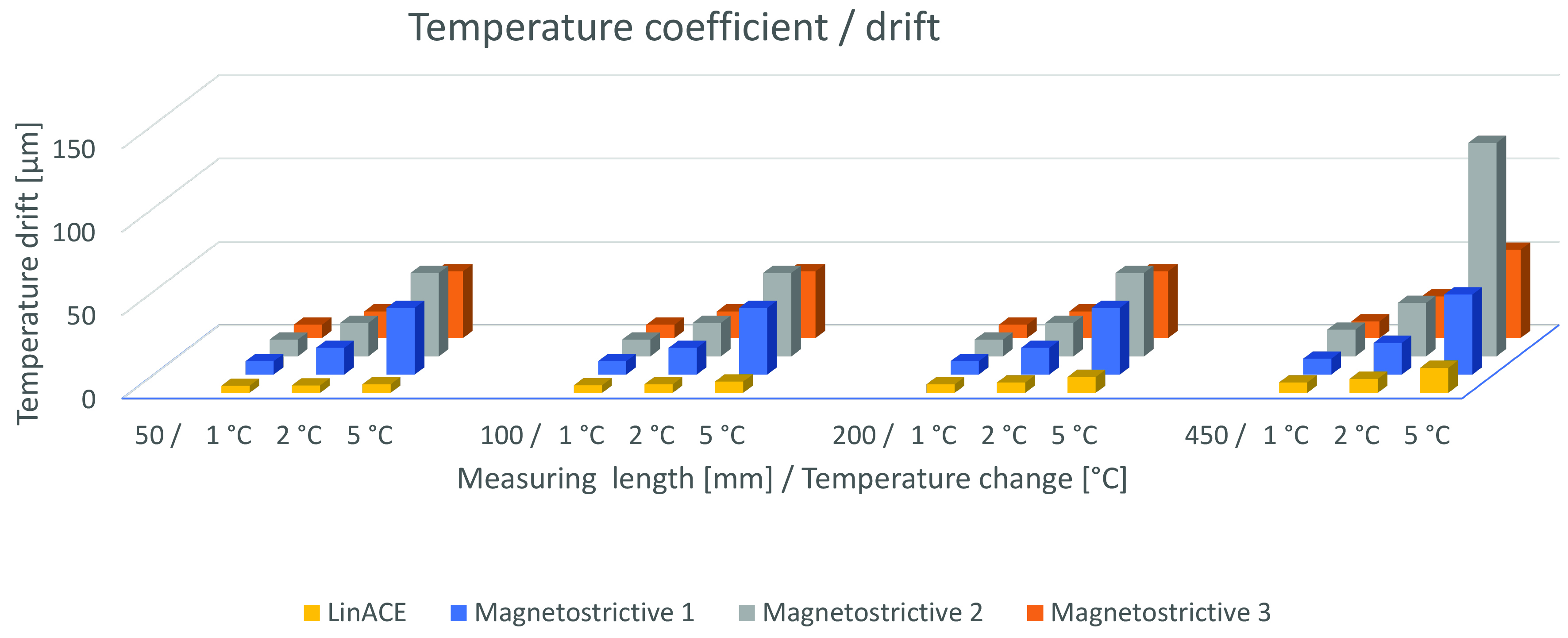
또한 다음 섹션 중 하나에서 설명한 것처럼, 자기 변형 센서의 온도 변이가 LinACE보다 크다는 점은 명확합니다.
소형디자인
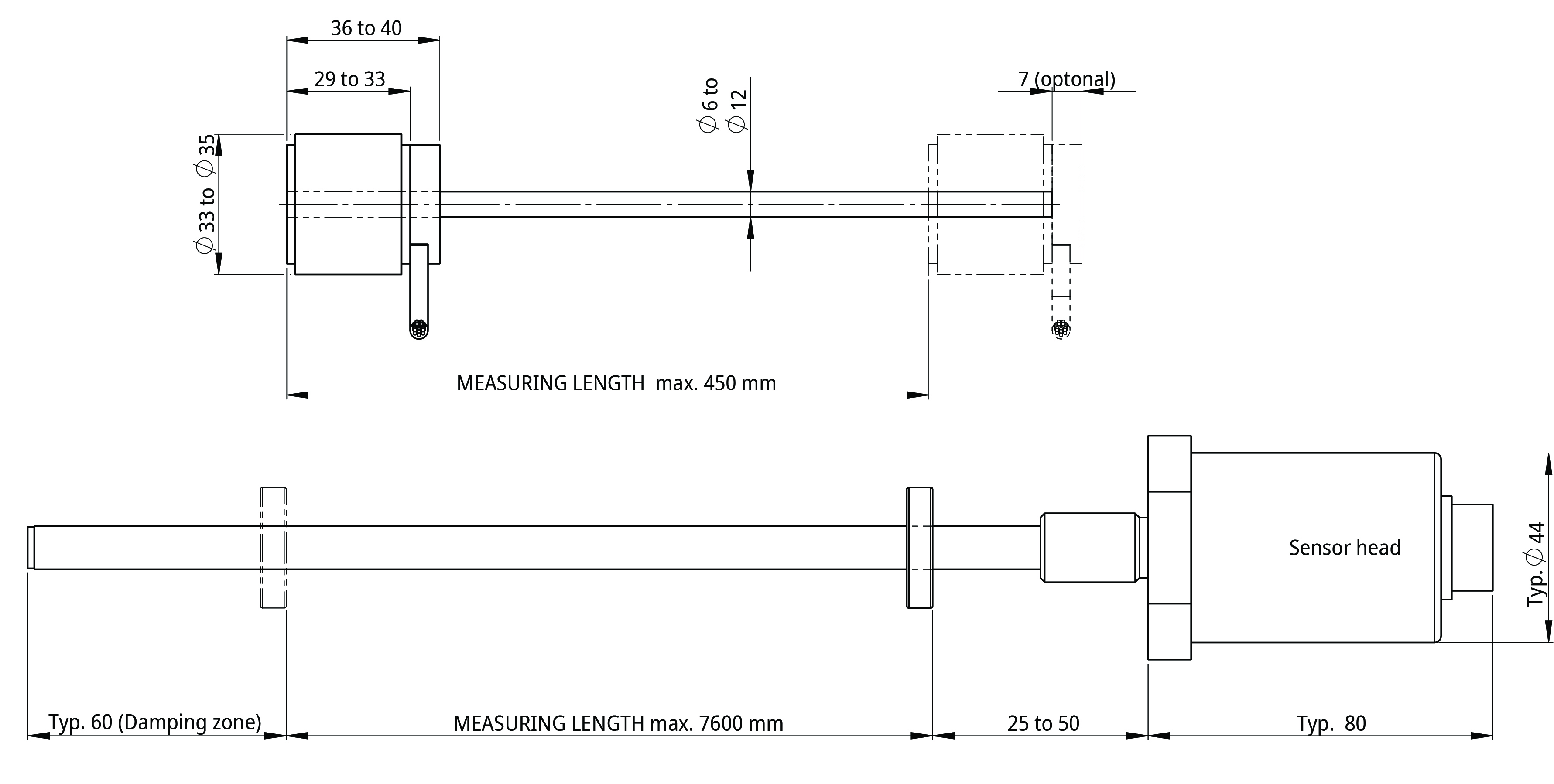
LinACE는 판독 헤드 길이가 29 mm부터 최대 40 mm까지이며 최대 직경은 35 mm입니다. 끝 부분에는 댐핑 존이 없습니다. 코딩된 강철 샤프트의 전체 길이는 위치 측정에 사용할 수 있습니다.
자기 변형 변환기는 일반적인 센서 헤드 길이가 약 80 mm이고, 센서 헤드부터 영점 위치까지 거리가 25 ~ 50 mm이고, 로드 끝 부분에서 댐핑 존이 60 mm입니다. 따라서 변환기의 총 길이는 측정 길이 + 150 ~ 200 mm입니다. 센서 헤드의 단면은 50 mm에 가까울 수 있습니다.
LinACE 엔코더 대 자기 변형 변환기 설계
내진동성
LinACE 엔코더는 충격과 진동에 대한 저항성이 있습니다. 앞뒤로 이동하는 동안 샤프트가 회전하더라도 엔코더의 위치가 유지됩니다.
자기 변형 엔코더는 도파관을 따라 이동하는 비틀림 스트레인 펄스를 기반으로 합니다. 따라서 이 엔코더는 진동에 민감합니다.
낮은 온도 변이
온도 변동 시 약간의 위치 변이가 발생할 수 있습니다. 일반적으로 자기 변형 변환기는 작은 측정 범위의 경우 온도 변이가 약 10 µm/K이고 긴 측정 길이의 경우 15 ppm/K ~ 35 ppm/K입니다.
LinACE 위치 측정값은 인코딩된 탄소강 샤프트와 판독 헤드의 알루미늄 하우징의 열 퍵창으로 인해 온도에 따라서만 바뀌게 됩니다. 이는 일반적으로 장치 프레임의 열 팽창 범위 이내에 있습니다.
온도 계수 / 변이
LinACE의 다른 이점
a) 더 넓은 온도 범위
LinACE의 온도 범위는 -30°C에서 +105°C로 확장되며, 대부분의 자기 변형 센서는 85°C에서 멈춥니다. 즉, 넓은 범위가 요구되는 분야에서는 LinACE가 적합합니다.
b) 낮은 자기 이력 현상
LinACE는 하나의 분해능 유닛보다 이력 현상이 적으며 자기 변형 센서의 일반적인 이력 현상은 약 10 µm입니다.
c) 더 낮은 전력 소비
LinACE와 자기 변형 센서 모두 전류 소비량이 약 100 mA입니다. 그러나 LinACE는 5 V의 공급 전압을 가지며 자기 변형 센서는 24 V가 필요합니다. 즉, 자기 변형 센서에 비해 LinACE의 전력 소비가 약 4-5배 더 적습니다.
사양 비교
| LinACE | 자기 변형 | |
| 측정 길이 | 20 mm ~ 450 mm | 50 mm ~ >4,000 mm |
| 엔코더 길이 | 측정 길이 + 29 mm ~ 40 mm | 측정 길이 + 150 mm ~ 200 mm |
| 분해능 | 최대 0.5 µm(20 mm 범위에서 >15비트) | 최대 0.5 µm |
| 정확도 | 최대 ±5 µm | ±50 µm |
| 자기이력 현상 | 분해능 유닛 미만 | <10 µm |
| 샘플링 주파수 | 4 kHz | 1 kHz |
| 출력 | 비동기식 시리얼, PWM, SSI, BiSS | 아날로그, SSI, ProfiNet, CANopen |
| 공급 전압 | 5 V | 24 V |
| 전력 사용량 | 통상 0.5 W* 최대 0.6 W* | 2.1 W ~ 3.6 W |
| IP 보호 | IP40 | IP68 |
| 온도 | -30 °C ~ +105 °C | -40 °C ~ +85 °C |
| 내진동성 | 40 g(내충격성 100 g) | 10 g ~ 20 g |


