LinACE™ vs. magnetostrictive encoders with SSI output
LinACE™ と磁歪センサーは、よく似た場面に使用できる機器ですが、両者間には重要な違いがあります。
磁歪センサーは、磁歪の原理を用いて位置を検出します。強磁性導波管、ポジションマグネット、緩衝帯、測定エレクトロニクス内蔵のひずみパルストランスデューサから構成されます。電流パルスが導波管に印加されて放射状の磁界が生じ、この磁界がポジションマグネットによって生じた磁界と相互に作用し合います。
磁界同士の相互作用により、ねじれゆがみパルスが生じ、導波管に沿って両方向に伝播していきます。パルスは導波管の片方の端部で減衰し、もう一方の端部でねじれゆがみコンバータによって電気信号に変換されます。
電流パルスの発生から電気信号の受信までにかかる時間から、ポジションマグネットの正確な位置が算出されます。
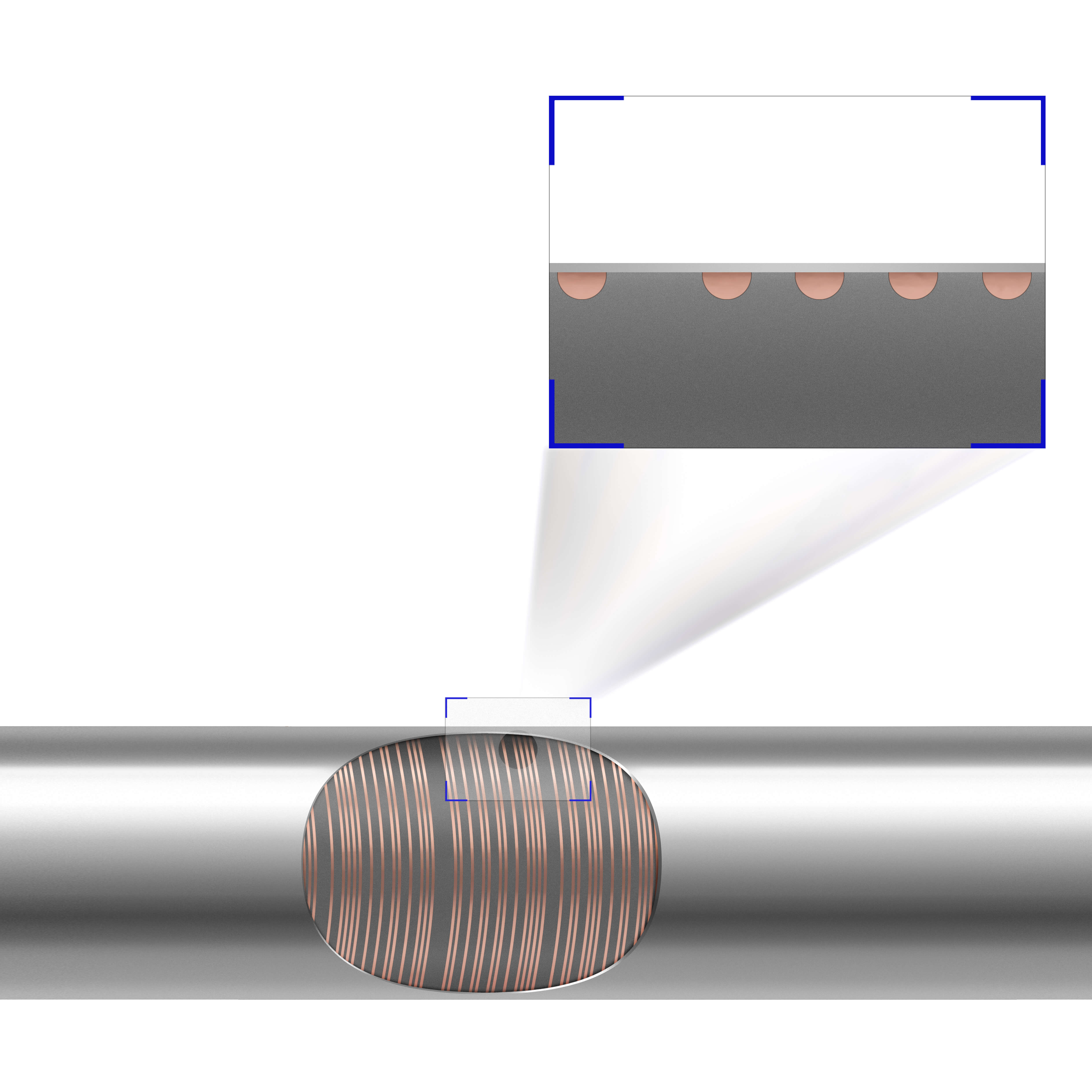
LinACE は、位置の暗号化を担うスケールと組み合わせて使うセンサーです。目盛りを刻んだシャフトをスケールとして使います。
LinACE がシャフトを読み取り、位置をデジタル信号に変換します。電源 ON 直後から位置を確立するアブソリュートエンコーダで、対応出力形式は、PWM、SSI および BiSS で、選択可能な分解能の範囲は 10µm~0.5µm、最高速度は 5m/s です。
磁歪センサーに対する LinACE のメリット
LinACE の詳細については、Web ページをご覧ください。"
高精度
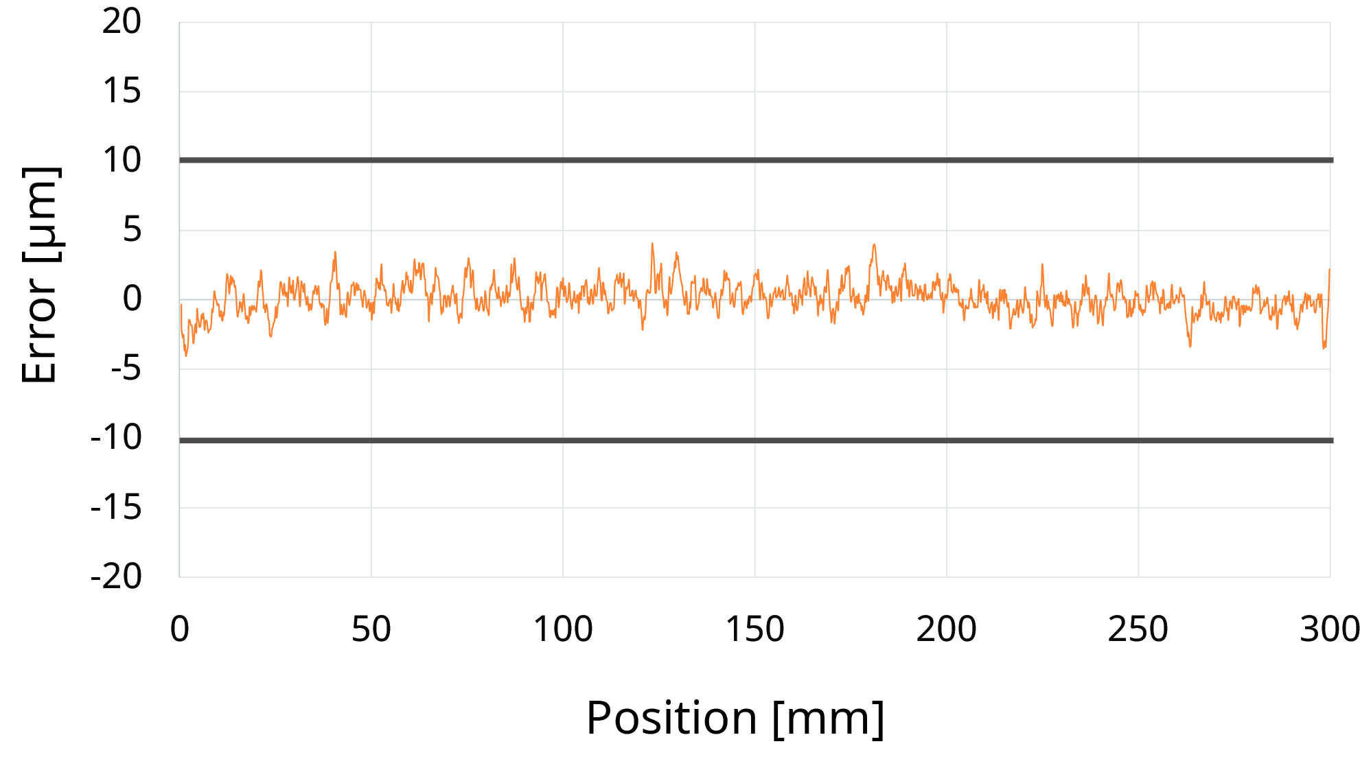
LinACE は、分解能 10µm~0.5µm、精度 ±100µm~±5µm でご用意しております。精度 ±5µm であれば、最大測定長は 100mm で、精度 ±10µm であれば 450mm です。
測定長 100mm の平均精度と ±5µm は以下のグラフのとおりです。
LinACE の精度グラフ
ただし、シャフトとアルミハウジングの熱膨張に起因する温度ドリフトを考慮する必要があります。
分解能が 0.5µm の磁歪センサーもありますが、磁歪センサーはリニアリティが規定されても、精度が規定されません。長さ 500mm まではリニアリティが平均で ±40µm または ±50µm ですが、
磁歪センサーの温度ドリフトは LinACE よりも高いことを留意しておく必要があります (以下のセクション参照)。
コンパクト設計
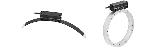
LinACE リードヘッドは長さ 29mm~40mm、最大直径 35mm で、端部に緩衝帯がないため、スチールシャフトの全長を測定域として使用できます。
磁歪トランスデューサはセンサーヘッドの長さがおよそ 80mm であることが一般的で、センサーヘッドから原点までが 25~50mm、シャフト端部のダンピングゾーンが 60mm です。そのためトランスデューサの全長としては測定長 + 150~200mm となります。センサーヘッドの断面は約 50mm です。
LinACE と磁歪トランスデューサの設計比較
![]()
振動への耐性
LinACE は衝撃と振動に対して耐性を備えています。前後への移動中にシャフトが回転しても、エンコーダの位置が維持されます。
磁歪センサーは、導波管沿いに移動するねじれゆがみパルスに依存するため、振動の影響を受けやすくなっています。
低温度ドリフト
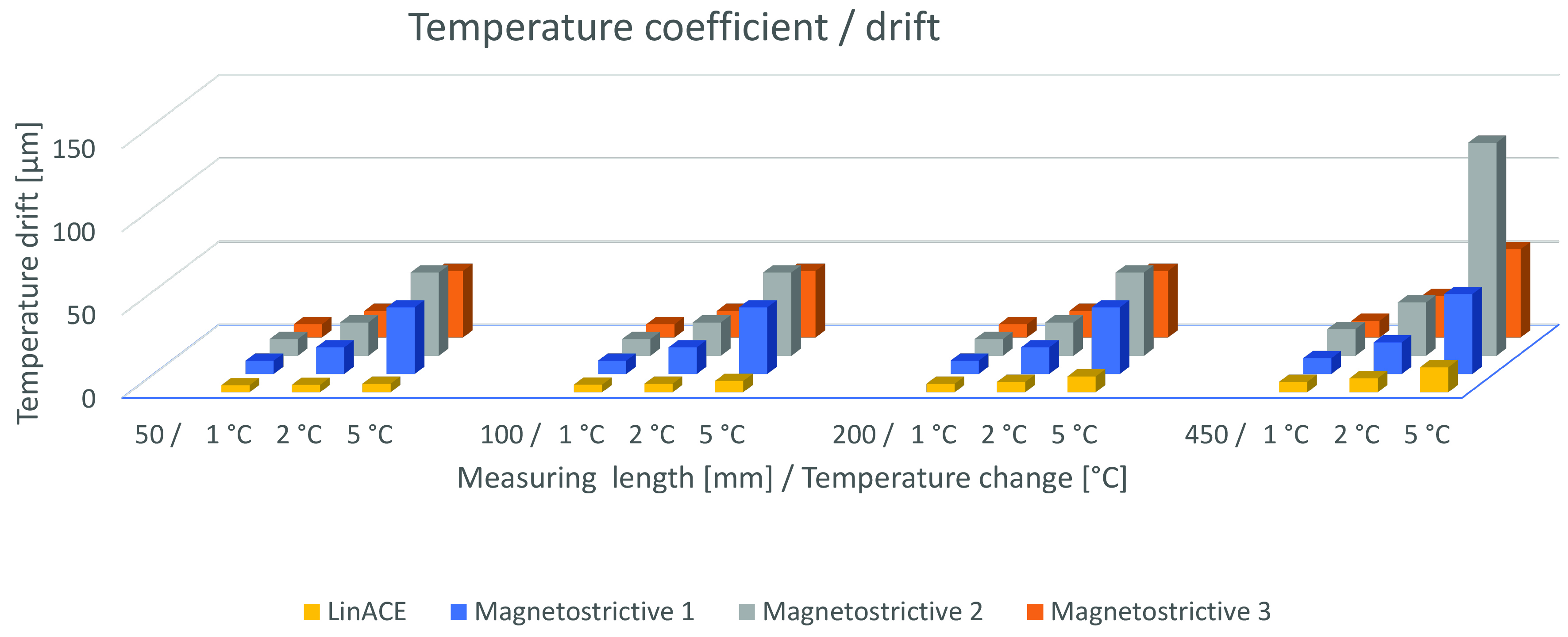
温度が変化すると、位置ずれが生じることが予想されます。磁歪トランスデューサの平均的な温度ドリフトは、測定長が短い場合は約 10µm/K で、長い場合で 15ppm/K~35ppm/K です。
温度が変化しても、LinACE の測定位置は、スチールシャフトとリードヘッドのアルミハウジングの熱膨張以外の影響を受けません。通常、機器のフレームの熱膨張範囲内に収まります。
熱膨張係数/ドリフト
LinACE の他のメリット
a) 広い温度範囲
LinACE の温度範囲は -30°C~+105°C で、たいていの磁歪センサーは 85°C までしか動作できません。LinACE のほうが多くの場面で使用できます。
b) 低ヒステリシス
LinACE のヒステリシスは分解能単位未満で、磁歪センサーの典型的なヒステリシスは約 10µm です。
c) 低電力消費
電流消費は、LinACE も磁歪センサーもどちらも約 100mA です。一方で、LinACE の供給電圧は 5V であるのに対し、磁歪センサーは 24V であるため、LinACE のほうが消費電力としては低く抑えられます。
仕様の比較
| LinACE | 磁歪センサー | |
| 測定長 | 20mm~450mm | 50mm~>4,000mm |
| エンコーダ長 | 測定長 + 29mm~40mm | 測定長 + 150mm~200mm |
| 分解能 | 最高 0.5µm (20mm で >15bit) | 最高 0.5µm |
| 精度 | 最高 ±5µm | ±50 μm |
| ヒステリシス | 分解能レベル | <10 μm |
| サンプリング周期 | 4 kHz | 1 kHz |
| 出力 | 非同期シリアル、PWM、SSI、BiSS | アナログ、SSI、ProfiNet、CANopen |
| 供給電圧 | 5 V | 24 V |
| 消費電力 | 平均 0.5W*、最大 0.6W* | 2.1W~3.6W |
| IP 保護 | IP40 | IP68 |
| 温度 | -30°C~+105°C | -40°C~+85°C |
| 振動への耐性 | 40G (最大 100G) | 10G~20G |