LinACE™ with digital outputs vs. LVDT sensor
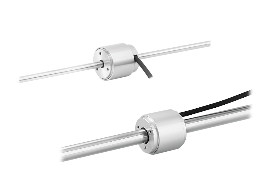
LinACE™ is an electromechanical sensor used to convert the linear motion of an object into an electrical signal.
Digital outputs have several benefits over analogue as they are less susceptible to EM interference, allow built-in self monitoring and can even employ error detecting codes such as CRC. All these results in higher reliability especially when longer cables are used.
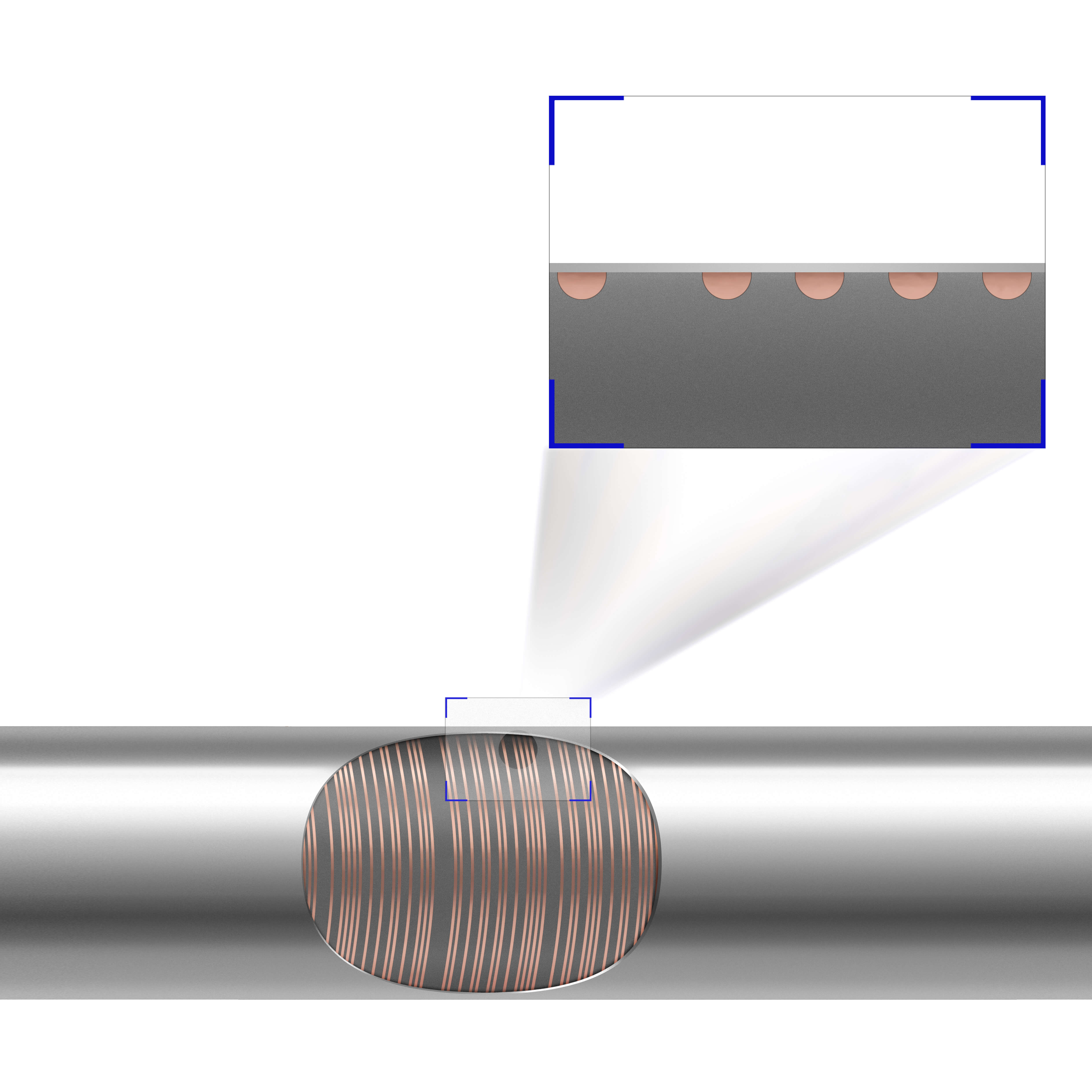
LVDT usually consists of three coils arranged around a tube. The middle coil is the primary coil and the two outer coils are the secondary coils. A ferromagnetic core slides along the axis.
When the core moves, the magnetic connection between the primary coil and the two secondary coils changes, resulting in a change in the induced voltages. The difference in the induced voltage in the secondary coils is converted into position information.
Why choose LinACE instead of LVDT?
- Low weight (no heavy coils are needed)
- Compact design
- Digital output and high level of diagnostics and reliability
- Temperature stability
- Low output ripple – signal noise
- Accuracy for measuring lengths 20 mm or more
- No pre- or post-travel
For more information on LinACE, visit the LinACE website.
Compact design
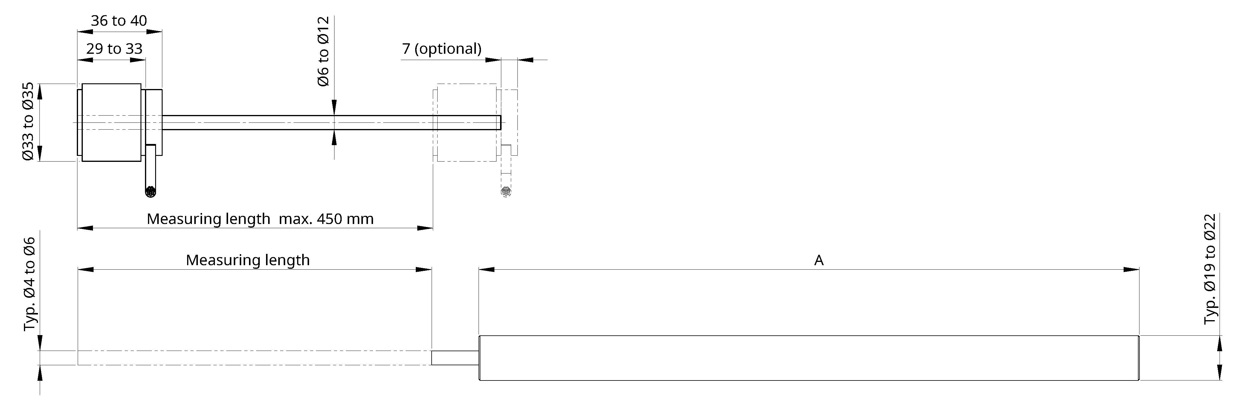
Unlike LVDT, the length of the LinACE readhead does not depend on the measuring length. LinACE has a readhead length of 29 mm to max. 40 mm and a diameter of max. 35 mm.
LVDT transducers require coils length greater than the measuring length. Therefore, the sensor head length increases parallel to the measuring length.
LVDT with a measuring length of 20 mm or more has a typical diameter of 19 mm or 22 mm. It can have integrated or separate processing electronics. With integrated processing electronics, the length of the sensor head is even greater. If the processing electronics are separate, this requires:
- Additional wiring,
- Space for installation and
- Additional cost.
LinACE vs. LVDT: readhead length and mass
| Measuring length [mm] | Length (mm) | Mass (g) | ||
| LinACE | LVDT (A) | LinACE | LVDT | |
| 20 | 29 | 140 | 94 | 130 |
| 100 | 29 | 230 | 111 | 265 |
| 150 | 29 | 280 | 122 | 325 |
| 300 | 29 | 450 | 144 | 520 |
- For LVDT: Estimated typical value (with integrated processing electronics).
- For LinACE: With axial cable output, 1 m cable and 6 mm coded shaft diameter.
Digital output and high level of diagnostics and reliability
LinACE encoders are available in asynchronous serial, PWM, SSI and BiSS output versions and offer a range of selectable resolutions from 10 µm to 0.5 µm at speeds up to 5 m/s.
The LinACE encoder has a built-in advanced self-monitoring function that continuously checks various internal parameters. Error reports, warnings and other status signals are available on all digital interfaces. No signal conditioner or additional electronics are required.
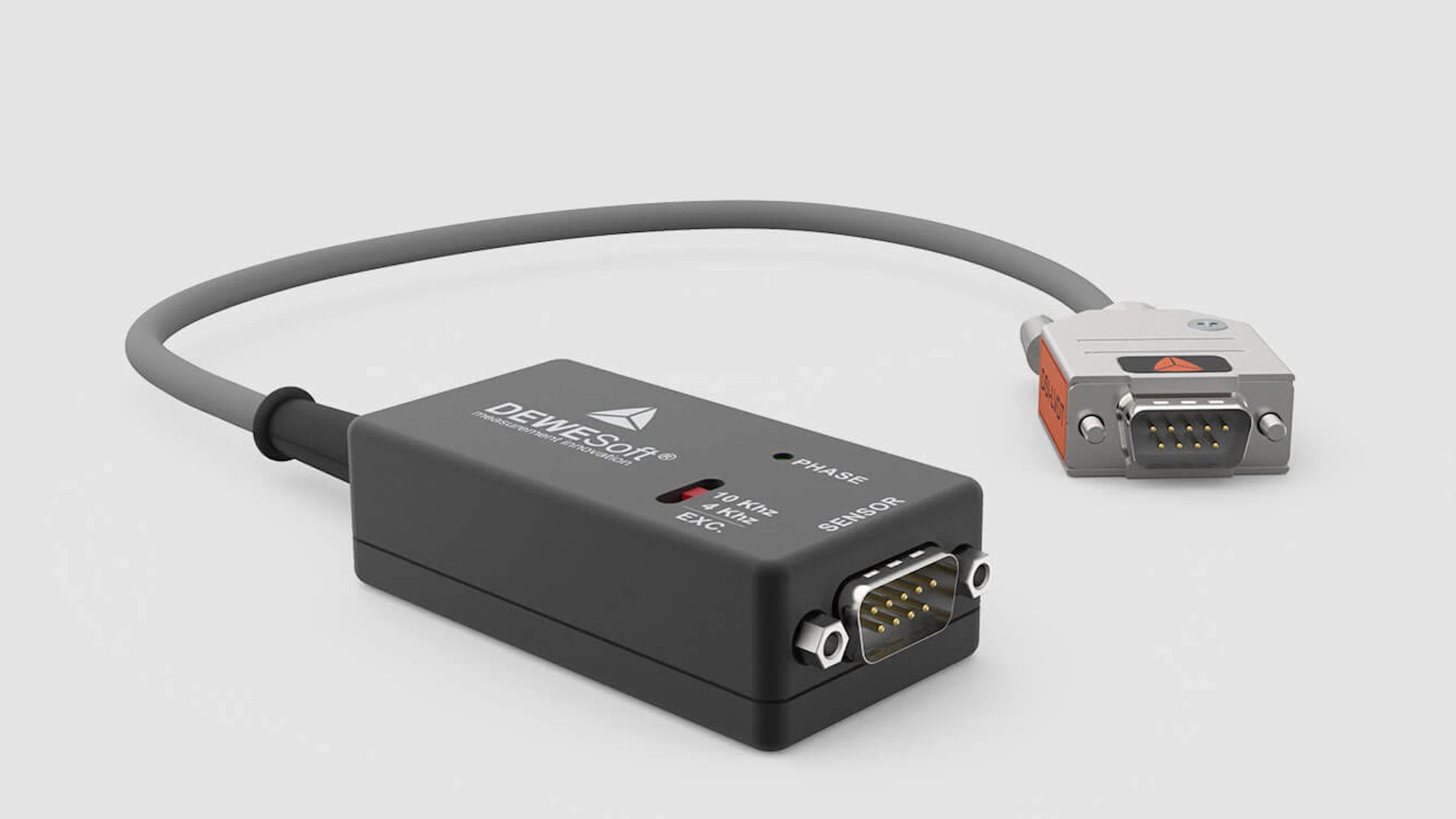
LVDT transducers normally have only analogue or LVDT outputs and no status information. In the case of an LVDT output, separate processing electronics (or a signal conditioner) is required.
Example of an LVDT signal conditioner by DEWESoft, DSI-LVDT Adapter:
Temperature stability
With temperature fluctuations, we can expect some positional drift. LVDT sensors typically give a temperature coefficient of 0.015% /K to 0.04%/K, which leads to considerable temperature drift, especially at longer measurement lengths.
The LinACE position measurement changes with temperature only due to the thermal expansion of the encoded carbon steel shaft and the aluminium housing of the read head. This is normally in the range of the thermal expansion of the device frame.
Output ripple – signal noise
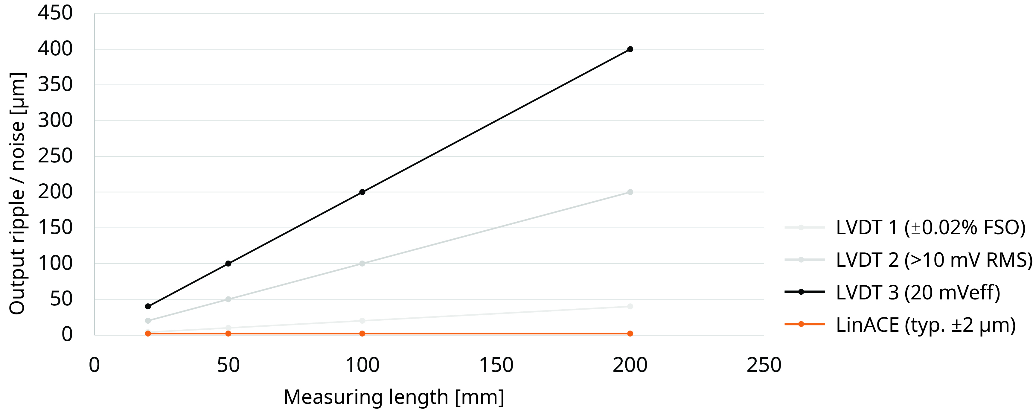
LVDTs typically give the output ripple or signal noise in mV (RMS) or mV (eff). The longer the measurement length, the greater the effect on accuracy. The output ripple or noise is usually lower in the middle of the measurement length and higher at the ends. For a measurement length of 150 mm, the noise level can be between 30 µm and 300 µm. For high-end LVDTs, it can be as low as 3 µm in the middle of the measurement range.
The signal noise of the LinACE sensor does not depend on the measuring length. The normal noise value is less than 2 µm.
Signal noise vs. measuring length of sensor
Accuracy for measuring lengths 20 mm or more
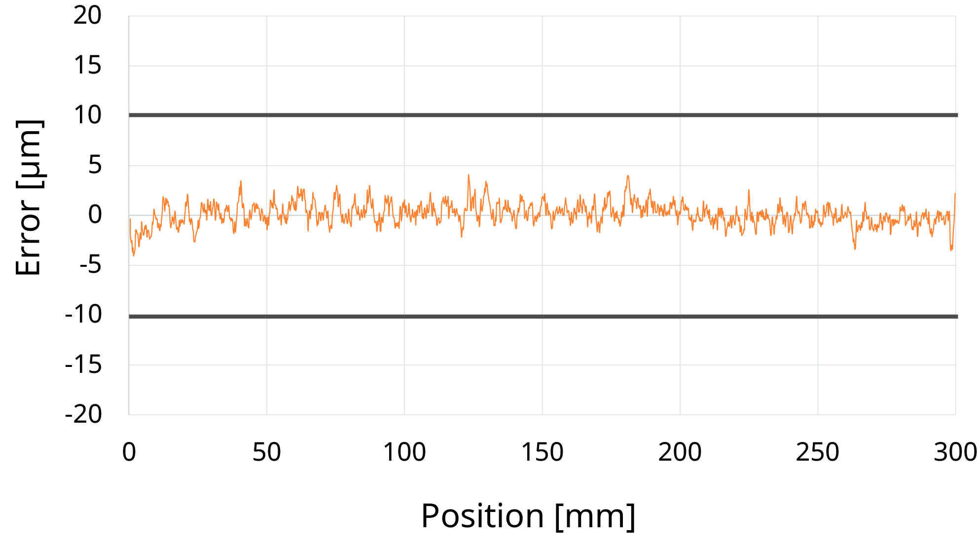
LinACE encoders are available with a resolution of 10 µm to 0.5 µm and an accuracy of ±100 µm to ±5 µm. An accuracy of ±5 µm is available up to a measuring length of 100 mm. And an accuracy of ±10 µm is available up to a measuring length of 450 mm. The LinACE accuracy diagram below shows a typical accuracy for a measuring length of 300 mm and an accuracy of ±10 µm.
However, we have to take into account the temperature drift due to the thermal expansion of the coded shaft and the aluminium housing.
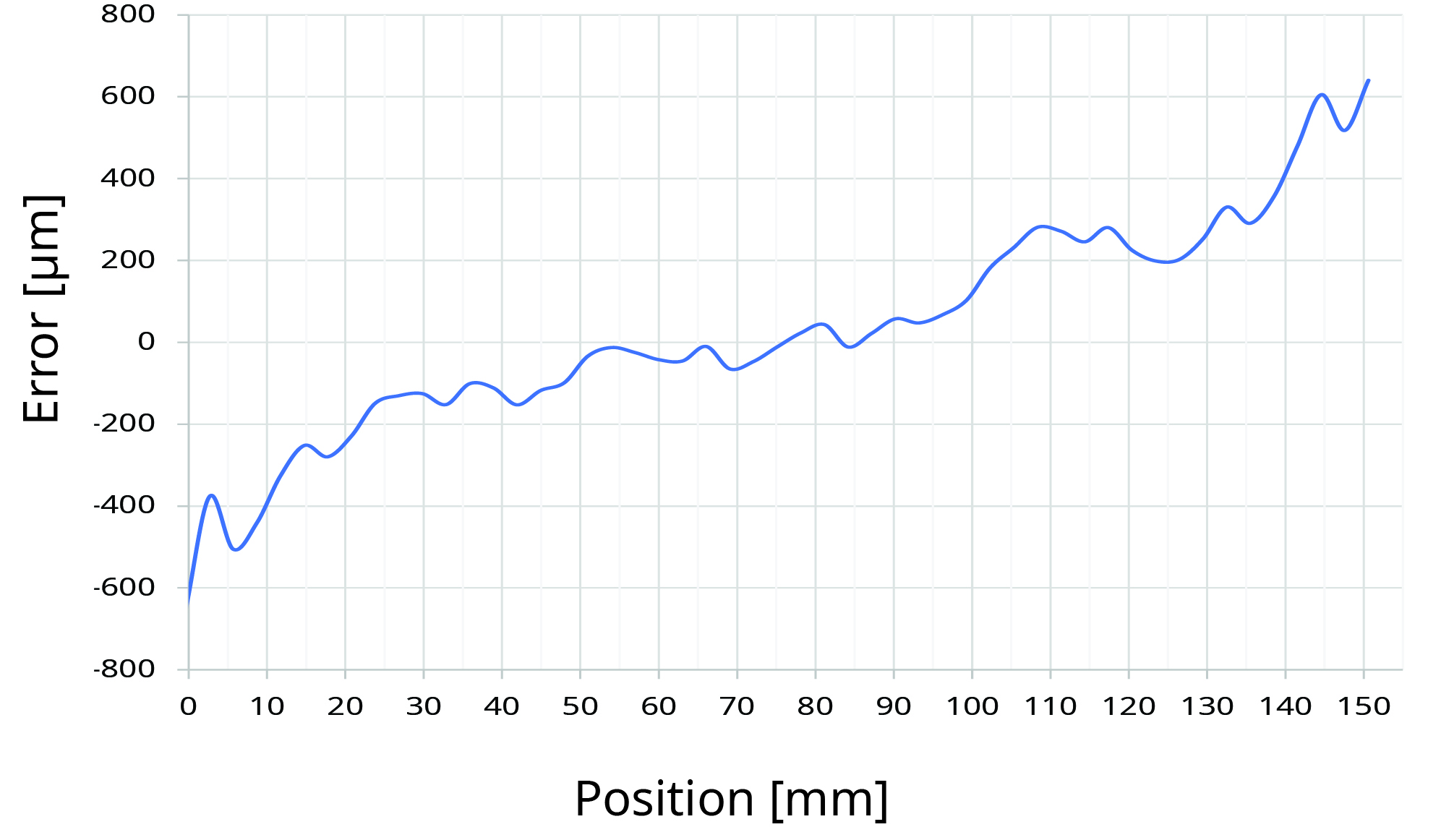
LVDT transducers have a typical non-linearity of 0.1 % to 0.5 %. Accuracy and resolution are therefore excellent up to a measuring range of 10 mm (±5 µm at ±5 mm travel with 0.1% non-linearity). At 100 mm travel, however, a non-linearity of 100 µm or more is to be expected. To achieve better linearity, additional calibration can be performed on the customer side.
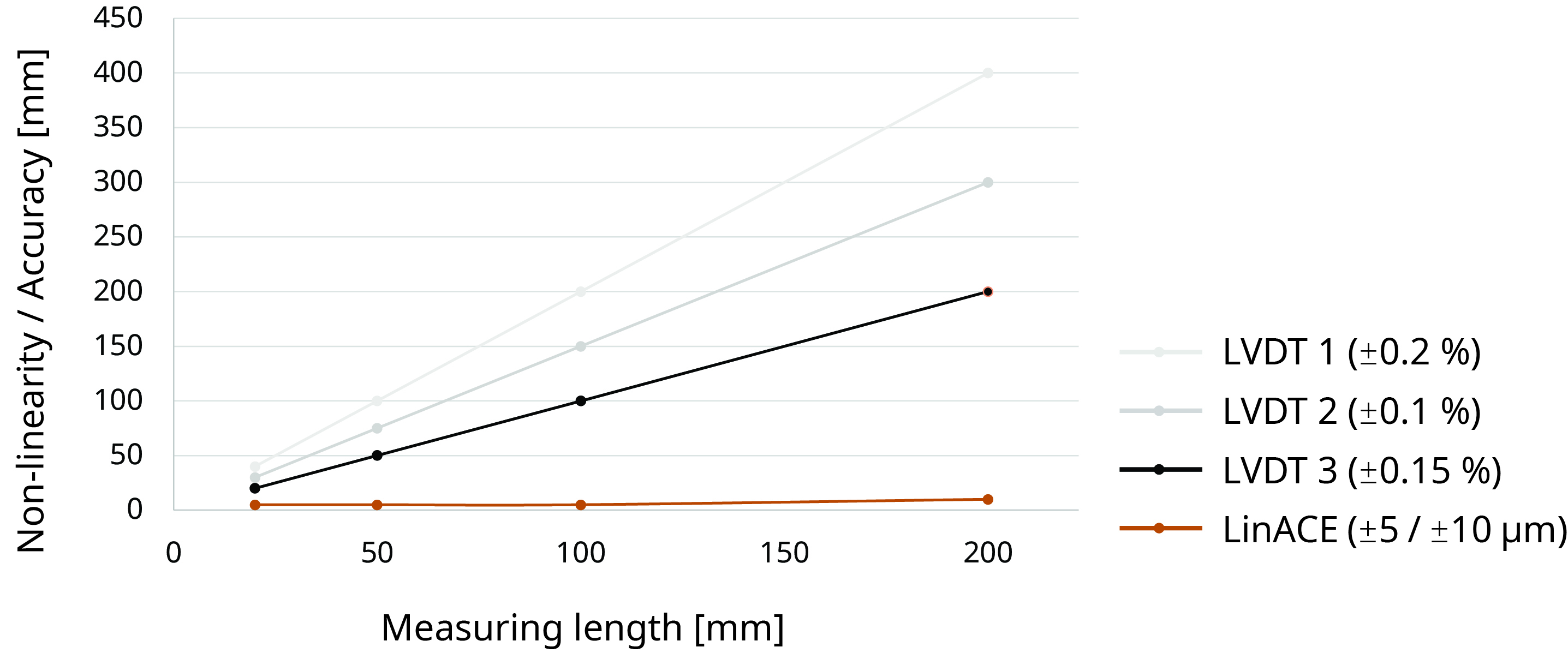
The LinACE vs. LVDT accuracy graph below shows LVDTs with non-linearity of 0.1%, 0.15% and 0.2%. As we can see, LinACE has a clear advantage in terms of accuracy at longer measurement lengths.
LinACE vs. LVDT accuracy graph
No pre- or post-travel
The LinACE encoder has no pre- or post-travel. The entire stroke from the beginning to the end of the coded shaft can be used without restrictions.
LVDT transducers have a very linear output over the specified range of core motion, but the sensor can be used over an extended range with reduced output linearity. This range is typically within a few mm.
- Pre-Travel: The mechanical movement from the fully outward position of the LVDT transducer (where the moving element is against a mechanical stop) to the beginning of the LVDT measurement range.
- Post-Travel: The mechanical movement from the end of the LVDT measurement range (inward) to the fully inward position where the moving element is against a mechanical stop.
Specifications comparison
| LinACE | LVDT | |
| Measuring length | From 20 mm to 450 mm | From 0.254 mm to 700 mm |
| Encoder length | Measuring length + 29 mm to 40 mm | Approx. measuring length x 2 |
| Resolution | To 0.5 µm (>15 bit on 20 mm range) | <15 bit |
| Accuracy | To ±5 µm | |
| Non-linearity | < 0.01 % on 100 mm range | 0.1 / 0.2 / 0.25 / 0.5 (% of full scale) |
| Repeatability | 1 µm | 0.01% to 0.1% (10 µm to 100 µm on 100 mm range) |
| Output bandwidth | 2000 Hz | 15 Hz to 500 Hz |
| Output | Asynchronous serial, PWM, SSI, BiSS | Analogue, RS485 |
| Supply voltage | 5 V | 5 V to 12 V or 10 V to 30 V |
| Power consumption |
Typical 500 mW* Max. 600 mW* |
300 mW to 700 mW |
| IP protection | IP40 | IP40 to IP68 |
| Temperature | From –30 °C to +105 °C |
From 0 °C to +65 °C or From –40 °C to +200 °C |
* Without output load.
Configure LinACE™ Download whitepaper


