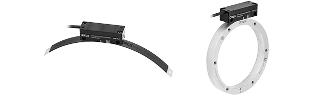
LinACE™ with digital outputs vs. LVDT sensor
LinACE™ 是電機感測器,可將物體的線性運動轉換成電氣訊號。
數位輸出在多方面比類比更出色,因其較不易受 EM 干涉影響、允許使用內建自我監控功能,甚至可以採用 CRC 等誤差偵測代碼。這些特色造成使用較長纜線時,數位輸出更加可靠。
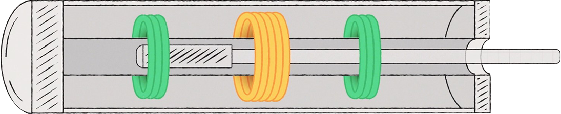
LVDT 通常由圍繞管芯的三個線圈組成。中央的線圈為主要線圈,其他兩個線圈為次要線圈。
鐵磁芯移動時,主要線圈和兩個次要線圈之間的磁性連接會產生變化,造成感應電壓變化。次要線圈的感應電壓差會轉換成位置資訊。
與 LVDT 感測器不同,LinACE 感測器會讀取硬鍍鉻實心鋼桿寫入的絕對碼,並將編碼位置轉換成數位訊號。
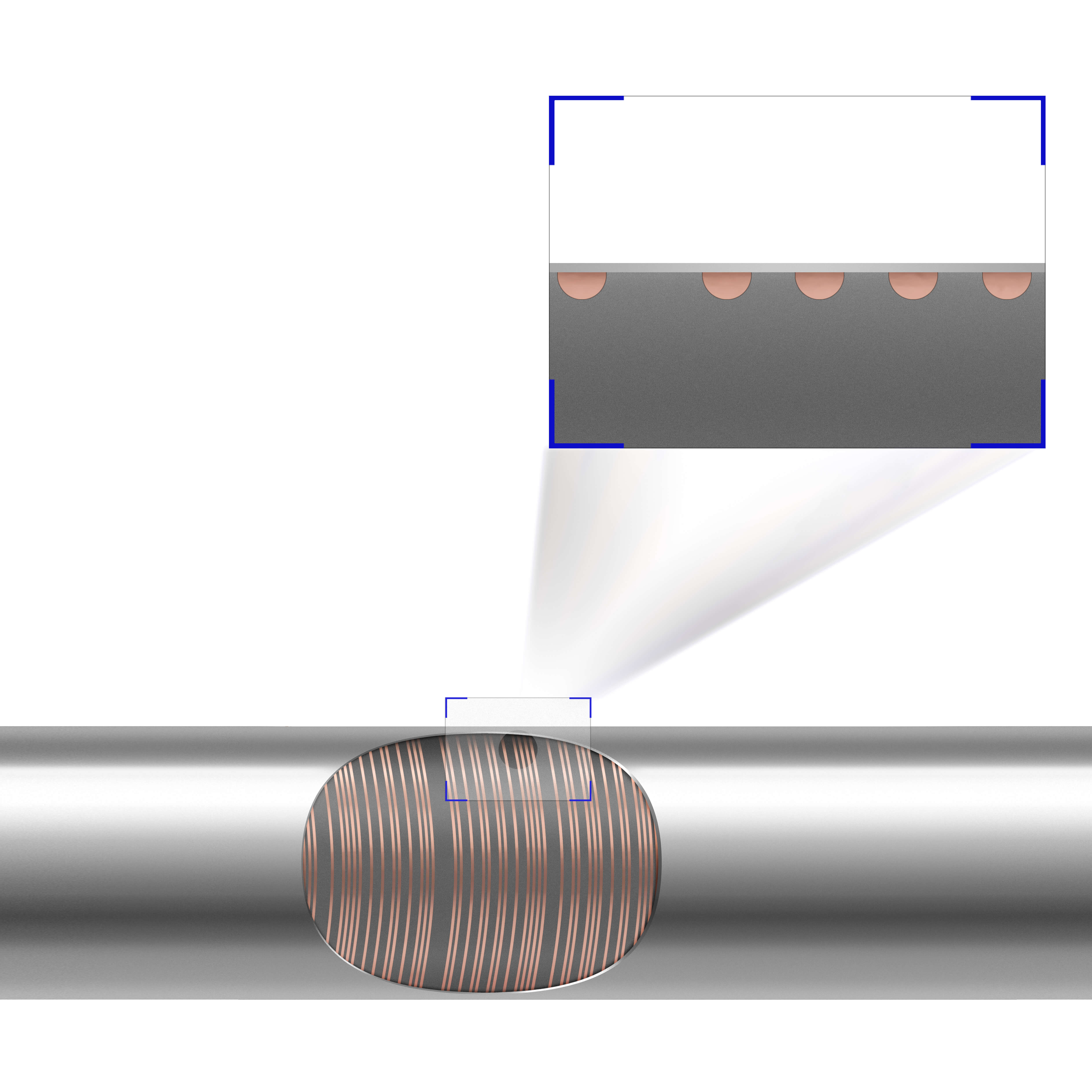
讀取編碼軸可針對根據感應電壓變化評估位置變更來提供多種優勢。
為什麼選擇 LinACE 而非 LVDT?
- 輕量(無需沉重的線圈)
- 小巧的設計
- 數位輸出和高階診斷功能與可靠性
- 溫度穩定性
- 低輸出漣波 - 訊號雜訊
- 量測長度 20 mm 或以上的精度
- 無前行程或後行程
有關 LinACE 的更多資訊,請造訪 LinACE 網站。
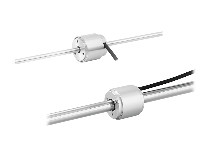
小巧的設計
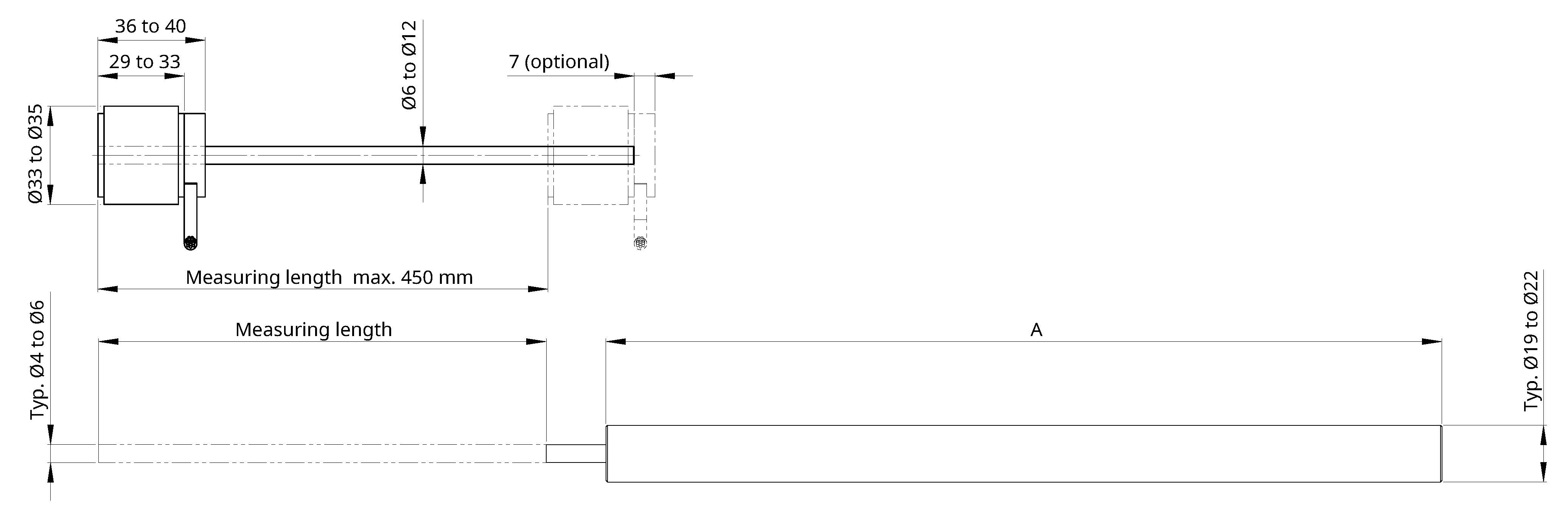
與 LVDT 不同,LinACE 讀頭的長度不受量測的長度影響。LinACE 的讀頭長度介於 29 mm 至 40 mm 之間,直徑最大 35 mm。
線圈長度需大於量測長度才能使用 LVDT 轉換器。因此,感測器測頭長度會隨量測長度增加。
若 LVDT 的量測長度為 20 mm 或以上,標準直徑為 19 mm 或 22 mm。可以使用整合或單獨處理的電子裝置。使用整合處理的電子裝置時,感測器測頭的長度會更大。如處理電子裝置為獨立式設計的,就需要:
- 額外配線、
- 安裝空間和
- 額外成本。
LinACE 與 LVDT 比較:讀頭長度和質量
| 量測長度 [mm] | 長度 (mm) | 質量 (g) | ||
| LinACE | LVDT (A) | LinACE | LVDT | |
| 20 | 29 | 140 | 94 | 130 |
| 100 | 29 | 230 | 111 | 265 |
| 150 | 29 | 280 | 122 | 325 |
| 300 | 29 | 450 | 144 | 520 |
- LVDT:預估標準值(使用整合處理電子裝置)。
- LinACE:含軸向纜線輸出、1 m 纜線和 6 mm 編碼軸直徑。
數位輸出和高階診斷功能與可靠性
LinACE 編碼器提供非同步序列、PWM、SSI 和 BiSS 輸出版本,並提供多種可選擇的解析度,範圍為 10 µm 至 0.5 µm,速度最高 5 m/s。
LinACE 編碼器內建進階自我監控功能,可持續檢查多項內部參數;所有數位介面皆提供錯誤報告、警告及其他狀態訊號。不需要訊號調節器或其他電子裝置。
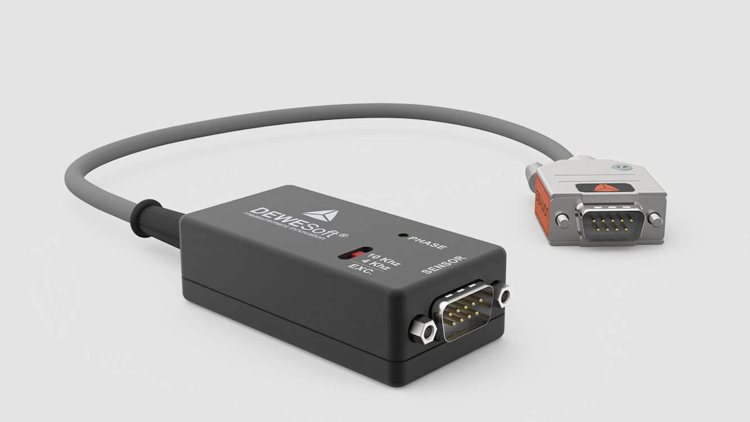
LVDT 轉換器通常只有類比或 LVDT 輸出,不會顯示狀態資訊。使用 LVDT 輸出時,需使用單獨處理電子裝置(或訊號調節器)。
DEWESoft 的 LVDT 訊號調節器範例,DSI-LVDT 轉接器:
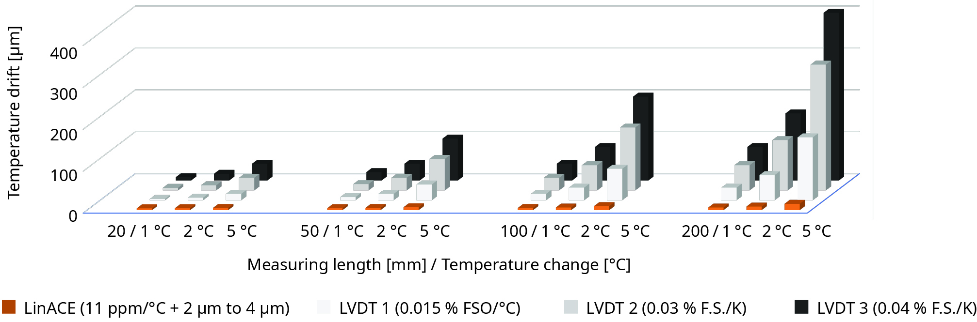
溫度穩定性
發生溫度波動時,我們可以預期導致位置產生漂移。LVDT 感測器的溫度係數通常為 0.015% /K 至 0.04%/K,會造成可觀的溫度漂移,尤其在量測長度較長時更是如此。
LinACE 位置量測只會因為編碼碳鋼軸和讀頭的鋁合金外殼發生熱膨脹,而隨著溫度漂移。其變化通常在裝置外框的熱膨脹範圍內。
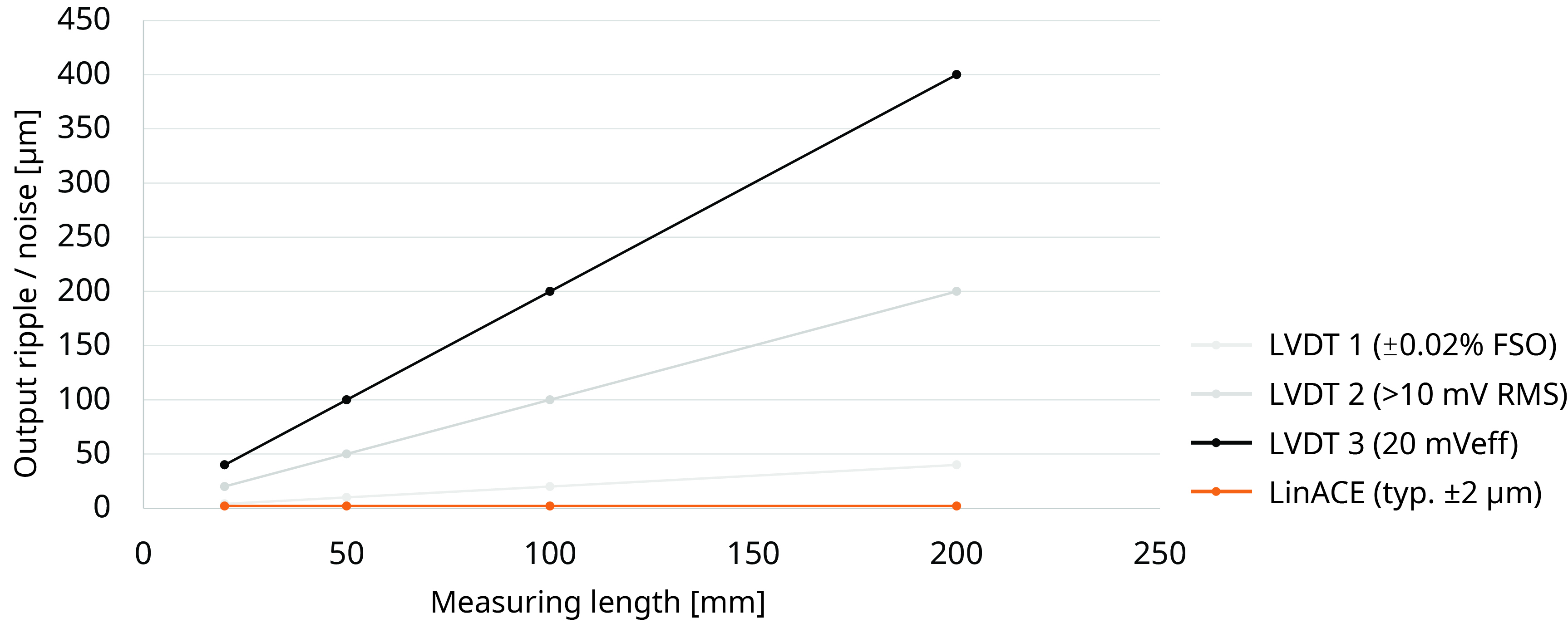
輸出漣波 - 訊號雜訊
LVDT 提供的輸出漣波或訊號雜訊,單位通常是 mV (RMS) 或 mV (eff) 。量測長度越長,對精度的影響越大。量測長度中段的輸出漣波或雜訊通常較低,兩端則較高。若量測長度為 150 mm,雜訊等級可介於 30 µm 至 300 µm。如為高階 LVDT,量測範圍中段的雜訊等級可低至 3 µm。
LinACE 感測器的訊號雜訊不受量測的長度影響。一般雜訊值低於 2 µm。
比較訊號雜訊與感測器量測長度
量測長度 20 mm 或以上的精度
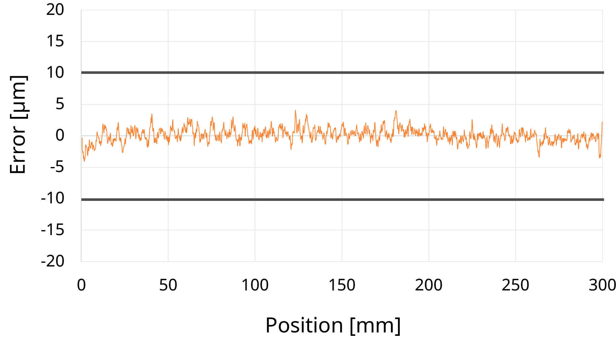
LinACE 編碼器具有 10 µm 至 0.5 µm 的解析度以及 ±100 µm 至 ±5 µm 的精度。±5 µm 的精度適用於最多 100 mm 的量測長度。±10 µm 的精度則適用於最多 450 mm 的量測長度。下方的 LinACE 精度圖顯示量測長度為 300 mm 且精度為 ±10 µm 時的標準精度。
不過,因為編碼軸與鋁合金外殼會熱膨脹,我們也必須考慮溫度漂移。
LVDT 轉換器標準非線性度為 0.1 % 至 0.5 %。因此,在量測範圍最多 10 mm 的情況下可以得出最佳精度和解析度(在 0.1% 非線性度的 ±5 mm 行程時為 ±5 µm)。不過,在 100 mm 行程時,預期為 100 µm 或以上的非線性度。為達到更好的線性度,客戶方需執行額外的校準。
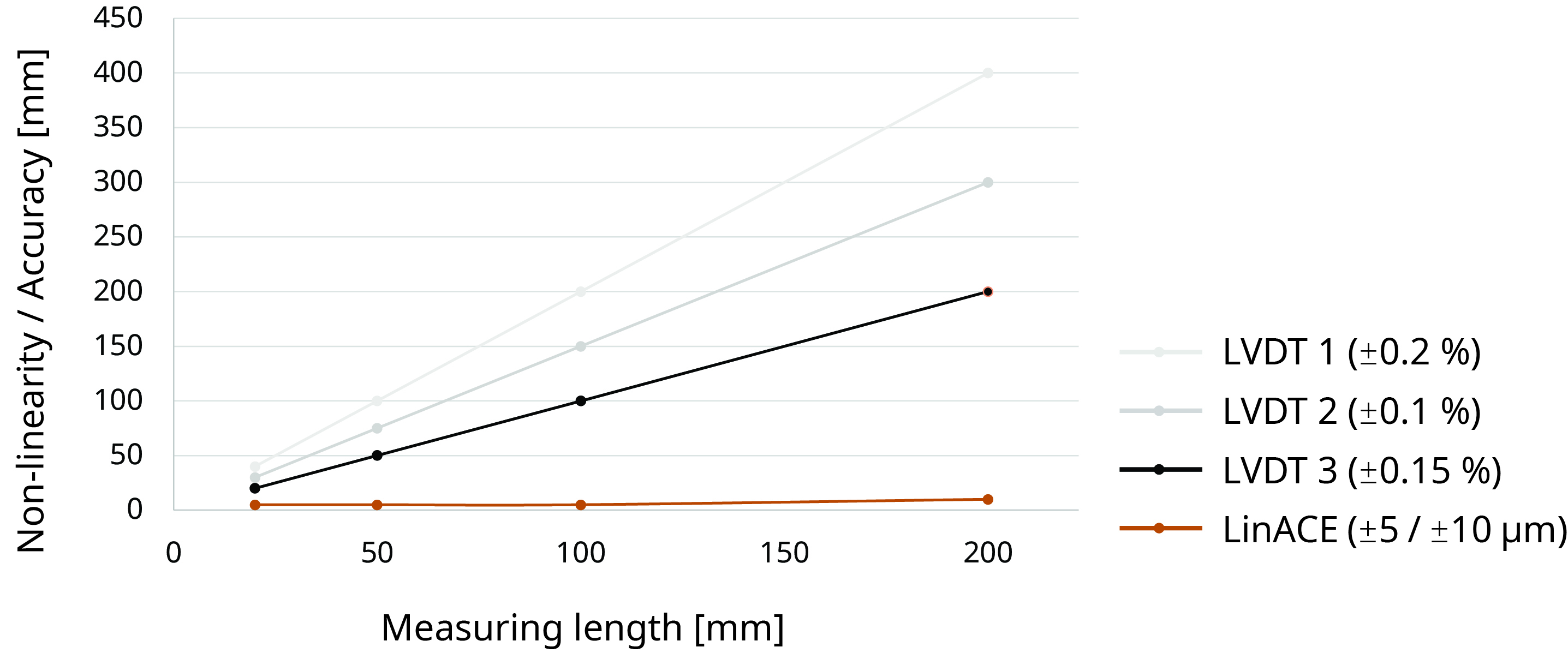
下方的 LinACE 與 LVDT 精度比較圖表顯示非線性度為 0.1%、0.15% 和 0.2% 時的 LVDT。我們可以看到,較長的量測長度時,LinACE 明顯在精度更具優勢。
LinACE 精度圖
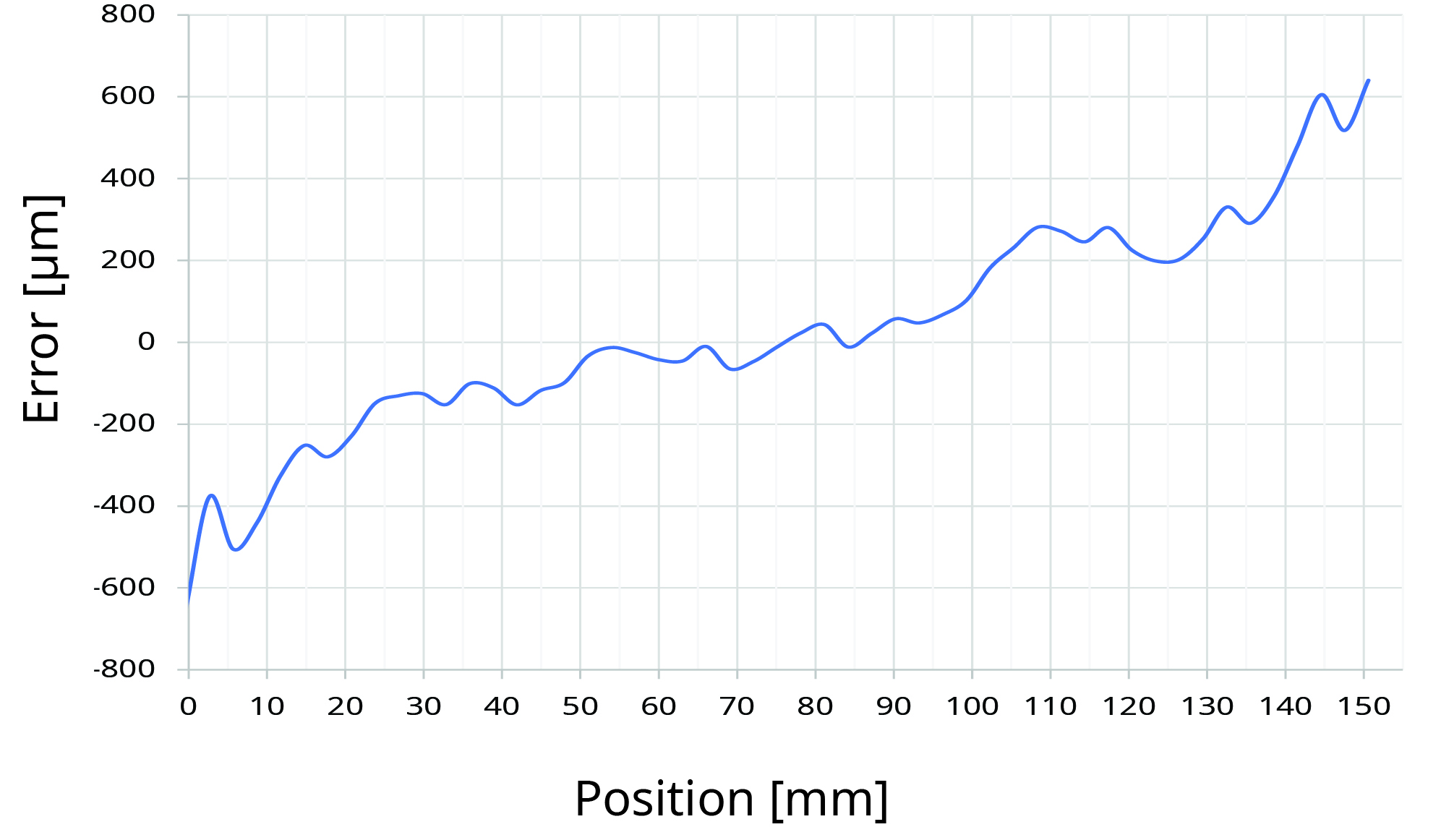
LVDT 精度圖
LinACE 與 LVDT 精度比較圖
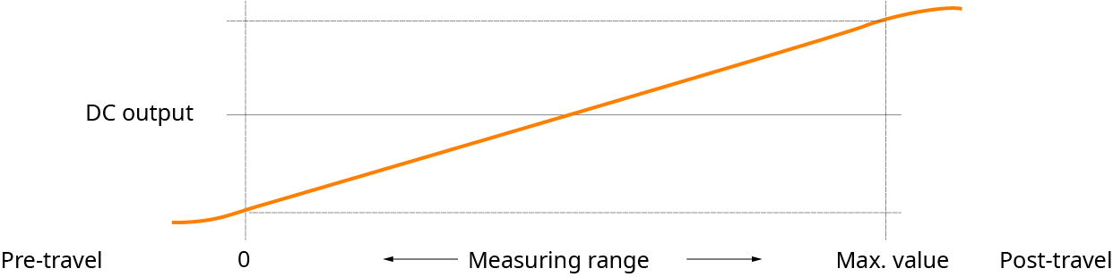
無前行程或後行程
LinACE 編碼器無前行程或後行程。從開始到結束的整個編碼軸使用過程可以不受限制。
LVDT 轉換器在特定芯動作範圍中具備非常線性的輸出,但感測器會用於較廣泛的範圍,導致輸出線性度下降。此範圍通常在幾 mm 之內。
- 前行程:從 LVDT 轉換器完全向外位置(移動元件位於機械式碼錶處),到 LVDT 量測範圍開頭的機械動作。
- 後行程:從 LVDT 量測範圍(向內)末端,到完全向內位置(移動元件位於機械式碼錶處)的機械動作。
規格比較
| LinACE | LVDT | |
| 量測長度 | 從 20 mm 至 450 mm | 從 0.254 mm 至 700 mm |
| 編碼器長度 | 測量長度 + 29 mm 至 40 mm | 約為量測長度 x 2 |
| 解析度 | 至 0.5 µm(20 mm 範圍時 >15 位元) | < 15 位元 |
| 準確度 | 至 ±5 µm | |
| 非線性度 | 100 mm 範圍時 < 0.01% | 0.1/0.2/0.25/0.5(整個磁性尺的百分比) |
| 重複性 | 1 µm | 0.01% 至 0.1%(100 mm 範圍時 10 µm 至 100 µm) |
| 輸出頻寬 | 2000 Hz | 15 Hz 至 500 Hz |
| 輸出 | 異步化序列、PWM、SSI、BiSS | 類比,RS485 |
| 供應電壓 | 5 V | 5 V 至 12 V 或 10 V 至 30 V |
| 耗電量 |
標準 500 mW* 最大600 mW* |
300 mW 至 700 mW |
| IP 防護等級 | IP40 | IP40 至 IP68 |
| 溫度 | -30°C 至 +105°C |
0 °C 至 +65°C 或 -40°C 至 +200°C |
* 無輸出負載。